3X-KVVS4-65B-R12
42-port tri-sector antenna, 6x617-960, 12x1695-2690MHz, 65°HPBW, 24x3300-3800MHz Beamformer, 12x RET
Features and Benefits
- Pole mounting kit not included. Separate pole mounting kit TS-MNT-TOP-370 available for pole diameter from 150 mm (5.9 inch) to 273 mm (10.7 inch). Please check Optional Mounting Kits section for more details
Specifications
General Specifications
| Antenna Type | DualPol® tri-sector |
| Band | Multiband |
| Calibration Connector Interface | M-LOC |
| Calibration Connector Quantity | 3 |
| Color | Light Gray (RAL 7035) |
| Grounding Type | RF connector inner conductor and body grounded to reflector and mounting bracket |
| Performance Note | Outdoor usage |
| Radome Material | ASA, UV stabilized |
| RF Connector Interface | 4.3-10 Female | M-LOC |
| RF Connector Location | Bottom |
| RF Connector Quantity, high band | 24 |
| RF Connector Quantity, mid band | 12 |
| RF Connector Quantity, low band | 6 |
| RF Connector Quantity, total | 42 |
Remote Electrical Tilt (RET) Information
| RET Hardware | CommRET v2 |
| RET Interface | 8-pin DIN Female | 8-pin DIN Male |
| RET Interface, quantity | 3 female | 3 male |
| Internal RET | High band (3) | Low band (3) | Mid band (6) |
| Power Consumption, active state, maximum | 10 W |
| Power Consumption, idle state, maximum | 2 W |
| Protocol | 3GPP/AISG 2.0 |
Dimensions
| Length | 2100 mm | 82.677 in |
| Net Weight, antenna only | 55.4 kg | 122.136 lb |
| Outer Diameter | 370 mm | 14.567 in |
Array Layout
| Click on image to enlarge. |

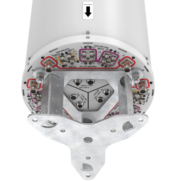
Port Configuration
| Click on image to enlarge. |

Electrical Specifications
| Impedance | 50 ohm |
| Operating Frequency Band | 617 – 960 MHz | 1695 – 2690 MHz | 3300 – 3800 MHz |
| Polarization | ±45° |
| Total Input Power, maximum | 1,200 W @ 50 °C |
Electrical Specifications
| R1-R3 | R1-R3 | R1-R3 | R1-R3 | Y1-Y6 | Y1-Y6 | Y1-Y6 | Y1-Y6 | P1-P3 | P1-P3 | |
| Frequency Band, MHz | 617–698 | 698–806 | 790–894 | 890–960 | 1695–1995 | 1920–2300 | 2300–2500 | 2490–2690 | 3300–3600 | 3600–3800 |
| RF Port | 1-6 | 1-6 | 1-6 | 1-6 | 7-18 | 7-18 | 7-18 | 7-18 | 19-42 | 19-42 |
| Gain at Mid Tilt, dBi | 14.5 | 14.8 | 15.4 | 15.7 | 16.4 | 17.1 | 17.2 | 17.1 | 15.3 | 15.3 |
| Beamwidth, Horizontal, degrees | 76 | 74 | 70 | 68 | 62 | 62 | 60 | 61 | 85 | 83 |
| Beamwidth, Vertical, degrees | 12.1 | 11 | 9.9 | 9.3 | 7.8 | 6.9 | 6.2 | 5.7 | 6.3 | 5.9 |
| Beam Tilt, degrees | 2–12 | 2–12 | 2–12 | 2–12 | 2–12 | 2–12 | 2–12 | 2–12 | 2–12 | 2–12 |
| USLS (First Lobe), dB | 16 | 20 | 22 | 18 | 18 | 18 | 18 | 17 | 14 | 13 |
| Front-to-Back Ratio at 180°, dB | 30 | 30 | 30 | 33 | 29 | 30 | 30 | 30 | 26 | 25 |
| Coupling level, Amp, Antenna port to Cal port, dB | 26 | 26 | ||||||||
| Coupling level, max Amp Δ, Antenna port to Cal port, dB | ±2 | ±2 | ||||||||
| Coupler, max Amp Δ, Antenna port to Cal port, dB | 0.9 | 0.9 | ||||||||
| Coupler, max Phase Δ, Antenna port to Cal port, degrees | 7 | 7 | ||||||||
| Isolation, Cross Polarization, dB | 25 | 25 | 25 | 25 | 25 | 25 | 25 | 25 | 25 | 25 |
| Isolation, Inter-band, dB | 25 | 25 | 25 | 25 | 25 | 25 | 25 | 25 | 25 | 25 |
| Isolation, Co-polarization, dB | 19 | 19 | ||||||||
| VSWR | Return loss, dB | 1.5 | 14.0 | 1.5 | 14.0 | 1.5 | 14.0 | 1.5 | 14.0 | 1.5 | 14.0 | 1.5 | 14.0 | 1.5 | 14.0 | 1.5 | 14.0 | 1.5 | 14.0 | 1.5 | 14.0 |
| PIM, 3rd Order, typical, 2 x 20 W, dBc | -150 | -150 | -150 | -150 | -150 | -150 | -150 | -150 | -140 | -140 |
| Input Power per Port at 50°C, maximum, watts | 300 | 300 | 300 | 300 | 250 | 250 | 200 | 200 | 75 | 75 |
Electrical Specifications, BASTA
| Frequency Band, MHz | 617–698 | 698–806 | 790–894 | 890–960 | 1695–1995 | 1920–2300 | 2300–2500 | 2490–2690 | 3300–3600 | 3600–3800 |
| Gain by all Beam Tilts, average, dBi | 14.4 | 14.8 | 15.3 | 15.5 | 16.3 | 16.9 | 17.0 | 16.9 | 15.0 | 15.0 |
| Gain by all Beam Tilts Tolerance, dB | ±0.3 | ±0.5 | ±0.5 | ±0.4 | ±0.7 | ±0.4 | ±0.4 | ±0.4 | ±1.3 | ±1.1 |
| Front-to-Back Total Power at 180° ± 30°, dB | 22 | 22 | 23 | 21 | 25 | 26 | 24 | 22 | 21 | 19 |
| CPR at Boresight, dB | 18 | 19 | 19 | 22 | 20 | 22 | 21 | 21 | 13 | 12 |
| CPR at Sector, dB | 13 | 10 | 10 | 9 | 8 | 6 | 7 | 9 | 6 | 6 |
Electrical Specifications, Broadcast 65
| Frequency Band, MHz | 617–698 | 698–806 | 790–894 | 890–960 | 1695–1995 | 1920–2300 | 2300–2500 | 2490–2690 | 3300–3600 | 3600–3800 |
| Gain, dBi | 17.9 | 17.9 | ||||||||
| Beamwidth, Horizontal at 3 dB, degrees | 65 | 65 | ||||||||
| Beamwidth, Vertical, degrees | 6.3 | 5.8 | ||||||||
| USLS (First Lobe), dB | 18 | 18 |
Electrical Specifications, Service Beam
| Frequency Band, MHz | 617–698 | 698–806 | 790–894 | 890–960 | 1695–1995 | 1920–2300 | 2300–2500 | 2490–2690 | 3300–3600 | 3600–3800 |
| Steered 0° Gain, dBi | 20.0 | 20.1 | ||||||||
| Steered 0° Beamwidth, Horizontal, degrees | 26 | 25 | ||||||||
| Steered 0° Front-to-Back Total Power at 180° ± 30°, dB | 29 | 27 | ||||||||
| Steered 0° Horizontal Sidelobe, dB | 12 | 11 | ||||||||
| Steered 30° Gain, dBi | 19.0 | 19.1 | ||||||||
| Steered 30° Beamwidth, Horizontal, degrees | 28 | 27 | ||||||||
| Steered 30° Front-to-Back Total Power at 180° ± 30°, dB | 28 | 25 |
Electrical Specifications, Soft Split
| Frequency Band, MHz | 617–698 | 698–806 | 790–894 | 890–960 | 1695–1995 | 1920–2300 | 2300–2500 | 2490–2690 | 3300–3600 | 3600–3800 |
| Gain, dBi | 18.8 | 19.1 | ||||||||
| Beamwidth, Horizontal, degrees | 32 | 29 | ||||||||
| Front-to-Back Total Power at 180° ± 30°, dB | 28 | 26 | ||||||||
| Horizontal Sidelobe, dB | 16 | 16 |
Mechanical Specifications
| Wind Loading @ Velocity, frontal | 489.0 N @ 150 km/h (109.9 lbf @ 150 km/h) |
| Wind Loading @ Velocity, lateral | 489.0 N @ 150 km/h (109.9 lbf @ 150 km/h) |
| Wind Loading @ Velocity, maximum | 489.0 N @ 150 km/h (109.9 lbf @ 150 km/h) |
| Wind Speed, maximum | 241 km/h (150 mph) |
Packaging and Weights
| Width, packed | 478 mm | 18.819 in |
| Depth, packed | 464 mm | 18.268 in |
| Length, packed | 2461 mm | 96.890 in |
| Weight, gross | 64.2 kg | 141.537 lb |
General Specifications
| Antenna Type | DualPol® tri-sector |
| Band | Multiband |
| Calibration Connector Interface | M-LOC |
| Calibration Connector Quantity | 3 |
| Color | Light Gray (RAL 7035) |
| Grounding Type | RF connector inner conductor and body grounded to reflector and mounting bracket |
| Performance Note | Outdoor usage |
| Radome Material | ASA, UV stabilized |
| RF Connector Interface | 4.3-10 Female | M-LOC |
| RF Connector Location | Bottom |
| RF Connector Quantity, high band | 24 |
| RF Connector Quantity, mid band | 12 |
| RF Connector Quantity, low band | 6 |
| RF Connector Quantity, total | 42 |
Remote Electrical Tilt (RET) Information
| RET Hardware | CommRET v2 |
| RET Interface | 8-pin DIN Female | 8-pin DIN Male |
| RET Interface, quantity | 3 female | 3 male |
| Internal RET | High band (3) | Low band (3) | Mid band (6) |
| Power Consumption, active state, maximum | 10 W |
| Power Consumption, idle state, maximum | 2 W |
| Protocol | 3GPP/AISG 2.0 |
Dimensions
| Length | 2100 mm | 82.677 in |
| Net Weight, antenna only | 55.4 kg | 122.136 lb |
| Outer Diameter | 370 mm | 14.567 in |
Electrical Specifications
| Impedance | 50 ohm |
| Operating Frequency Band | 617 – 960 MHz | 1695 – 2690 MHz | 3300 – 3800 MHz |
| Polarization | ±45° |
| Total Input Power, maximum | 1,200 W @ 50 °C |
Electrical Specifications
| R1-R3 | R1-R3 | R1-R3 | R1-R3 | Y1-Y6 | Y1-Y6 | Y1-Y6 | Y1-Y6 | P1-P3 | P1-P3 | |
| Frequency Band, MHz | 617–698 | 698–806 | 790–894 | 890–960 | 1695–1995 | 1920–2300 | 2300–2500 | 2490–2690 | 3300–3600 | 3600–3800 |
| RF Port | 1-6 | 1-6 | 1-6 | 1-6 | 7-18 | 7-18 | 7-18 | 7-18 | 19-42 | 19-42 |
| Gain at Mid Tilt, dBi | 14.5 | 14.8 | 15.4 | 15.7 | 16.4 | 17.1 | 17.2 | 17.1 | 15.3 | 15.3 |
| Beamwidth, Horizontal, degrees | 76 | 74 | 70 | 68 | 62 | 62 | 60 | 61 | 85 | 83 |
| Beamwidth, Vertical, degrees | 12.1 | 11 | 9.9 | 9.3 | 7.8 | 6.9 | 6.2 | 5.7 | 6.3 | 5.9 |
| Beam Tilt, degrees | 2–12 | 2–12 | 2–12 | 2–12 | 2–12 | 2–12 | 2–12 | 2–12 | 2–12 | 2–12 |
| USLS (First Lobe), dB | 16 | 20 | 22 | 18 | 18 | 18 | 18 | 17 | 14 | 13 |
| Front-to-Back Ratio at 180°, dB | 30 | 30 | 30 | 33 | 29 | 30 | 30 | 30 | 26 | 25 |
| Coupling level, Amp, Antenna port to Cal port, dB | 26 | 26 | ||||||||
| Coupling level, max Amp Δ, Antenna port to Cal port, dB | ±2 | ±2 | ||||||||
| Coupler, max Amp Δ, Antenna port to Cal port, dB | 0.9 | 0.9 | ||||||||
| Coupler, max Phase Δ, Antenna port to Cal port, degrees | 7 | 7 | ||||||||
| Isolation, Cross Polarization, dB | 25 | 25 | 25 | 25 | 25 | 25 | 25 | 25 | 25 | 25 |
| Isolation, Inter-band, dB | 25 | 25 | 25 | 25 | 25 | 25 | 25 | 25 | 25 | 25 |
| Isolation, Co-polarization, dB | 19 | 19 | ||||||||
| VSWR | Return loss, dB | 1.5 | 14.0 | 1.5 | 14.0 | 1.5 | 14.0 | 1.5 | 14.0 | 1.5 | 14.0 | 1.5 | 14.0 | 1.5 | 14.0 | 1.5 | 14.0 | 1.5 | 14.0 | 1.5 | 14.0 |
| PIM, 3rd Order, typical, 2 x 20 W, dBc | -150 | -150 | -150 | -150 | -150 | -150 | -150 | -150 | -140 | -140 |
| Input Power per Port at 50°C, maximum, watts | 300 | 300 | 300 | 300 | 250 | 250 | 200 | 200 | 75 | 75 |
Electrical Specifications, BASTA
| Frequency Band, MHz | 617–698 | 698–806 | 790–894 | 890–960 | 1695–1995 | 1920–2300 | 2300–2500 | 2490–2690 | 3300–3600 | 3600–3800 |
| Gain by all Beam Tilts, average, dBi | 14.4 | 14.8 | 15.3 | 15.5 | 16.3 | 16.9 | 17.0 | 16.9 | 15.0 | 15.0 |
| Gain by all Beam Tilts Tolerance, dB | ±0.3 | ±0.5 | ±0.5 | ±0.4 | ±0.7 | ±0.4 | ±0.4 | ±0.4 | ±1.3 | ±1.1 |
| Front-to-Back Total Power at 180° ± 30°, dB | 22 | 22 | 23 | 21 | 25 | 26 | 24 | 22 | 21 | 19 |
| CPR at Boresight, dB | 18 | 19 | 19 | 22 | 20 | 22 | 21 | 21 | 13 | 12 |
| CPR at Sector, dB | 13 | 10 | 10 | 9 | 8 | 6 | 7 | 9 | 6 | 6 |
Electrical Specifications, Broadcast 65
| Frequency Band, MHz | 617–698 | 698–806 | 790–894 | 890–960 | 1695–1995 | 1920–2300 | 2300–2500 | 2490–2690 | 3300–3600 | 3600–3800 |
| Gain, dBi | 17.9 | 17.9 | ||||||||
| Beamwidth, Horizontal at 3 dB, degrees | 65 | 65 | ||||||||
| Beamwidth, Vertical, degrees | 6.3 | 5.8 | ||||||||
| USLS (First Lobe), dB | 18 | 18 |
Electrical Specifications, Service Beam
| Frequency Band, MHz | 617–698 | 698–806 | 790–894 | 890–960 | 1695–1995 | 1920–2300 | 2300–2500 | 2490–2690 | 3300–3600 | 3600–3800 |
| Steered 0° Gain, dBi | 20.0 | 20.1 | ||||||||
| Steered 0° Beamwidth, Horizontal, degrees | 26 | 25 | ||||||||
| Steered 0° Front-to-Back Total Power at 180° ± 30°, dB | 29 | 27 | ||||||||
| Steered 0° Horizontal Sidelobe, dB | 12 | 11 | ||||||||
| Steered 30° Gain, dBi | 19.0 | 19.1 | ||||||||
| Steered 30° Beamwidth, Horizontal, degrees | 28 | 27 | ||||||||
| Steered 30° Front-to-Back Total Power at 180° ± 30°, dB | 28 | 25 |
Electrical Specifications, Soft Split
| Frequency Band, MHz | 617–698 | 698–806 | 790–894 | 890–960 | 1695–1995 | 1920–2300 | 2300–2500 | 2490–2690 | 3300–3600 | 3600–3800 |
| Gain, dBi | 18.8 | 19.1 | ||||||||
| Beamwidth, Horizontal, degrees | 32 | 29 | ||||||||
| Front-to-Back Total Power at 180° ± 30°, dB | 28 | 26 | ||||||||
| Horizontal Sidelobe, dB | 16 | 16 |
Mechanical Specifications
| Wind Loading @ Velocity, frontal | 489.0 N @ 150 km/h (109.9 lbf @ 150 km/h) |
| Wind Loading @ Velocity, lateral | 489.0 N @ 150 km/h (109.9 lbf @ 150 km/h) |
| Wind Loading @ Velocity, maximum | 489.0 N @ 150 km/h (109.9 lbf @ 150 km/h) |
| Wind Speed, maximum | 241 km/h (150 mph) |
Packaging and Weights
| Width, packed | 478 mm | 18.819 in |
| Depth, packed | 464 mm | 18.268 in |
| Length, packed | 2461 mm | 96.890 in |
| Weight, gross | 64.2 kg | 141.537 lb |
| Click on image to enlarge. |
| Click on image to enlarge. |
Documentation & Downloads
Assembly Drawing
Product Information
Product Specification
Assembly Drawing
Product Compliance Documentation
Product Information
Product Specification
Other Ways to Browse
