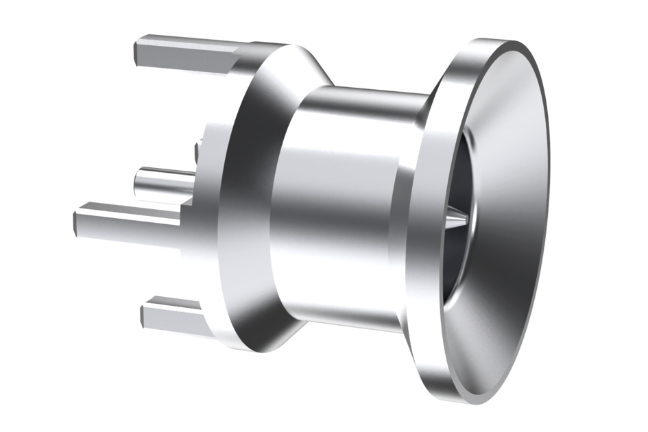
B2BYM-PCB
1.5-3.5 Male Straight B2B, PCB Type
Specifications
Product Classification
| Product Type | Device connector |
General Specifications
| Body Style | Straight |
| Inner Contact Attachment Method | Solder |
| Inner Contact Plating | Silver |
| Interface | 1.5-3.5 Male |
| Mounting Angle | Straight |
| Outer Contact Plating | Tin | Trimetal |
Dimensions
| Height | 9 mm | 0.354 in |
| Width | 9 mm | 0.354 in |
| Length | 9.8 mm | 0.386 in |
| Diameter | 9 mm | 0.354 in |
Outline Drawing
| Click on image to enlarge. |

Electrical Specifications
| 3rd Order IMD at Frequency | -110 dBm @ 3500 MHz | -112 dBm @ 1800 MHz | -112 dBm @ 910 MHz |
| 3rd Order IMD Test Method | Two +43 dBm carriers |
| Insertion Loss, maximum | 0.1 dB |
| Connector Impedance | 50 ohm |
| dc Test Voltage | 1000 V |
| Inner Contact Resistance, maximum | 2 mOhm |
| Insulation Resistance, minimum | 5000 mOhm |
| Operating Frequency Band | 0 – 6000 MHz |
| Outer Contact Resistance, maximum | 2 mOhm |
| RF Operating Voltage, maximum (vrms) | 500 V |
Return Loss/VSWR
| Frequency Band | VSWR | Return Loss (dB) |
| 450–2200 MHz | 1.065 | 30.04 |
| 2200–3800 MHz | 1.065 | 30.04 |
| 3800–4200 MHz | 1.083 | 27.99 |
| 4200–6000 MHz | 1.222 | 20.01 |
Mechanical Specifications
| PCB Attachment | Through-hole |
| Insertion Force | 15 N | 3.372 lbf |
| Interface Durability | 100 cycles |
| Interface Durability Method | IEC 61169-4:17 |
| Mechanical Shock Test Method | IEC 60068-2-27 |
| Radial Float/Misalignment | 2.7 ° |
Environmental Specifications
| Operating Temperature | -55 °C to +85 °C (-67 °F to +185 °F) |
| Storage Temperature | -65 °C to +125 °C (-85 °F to +257 °F) |
| Attenuation, Ambient Temperature | 20 °C | 68 °F |
| Average Power, Ambient Temperature | 40 °C | 104 °F |
| Average Power, Inner Conductor Temperature | 100 °C | 212 °F |
| Corrosion Test Method | IEC 60068-2-11 |
| Thermal Shock Test Method | IEC 60068-2-14 |
| Vibration Test Method | IEC 60068-2-6 |
Packaging and Weights
| Weight, net | 1.33 g | 0.003 lb |
Product Classification
| Product Type | Device connector |
General Specifications
| Body Style | Straight |
| Inner Contact Attachment Method | Solder |
| Inner Contact Plating | Silver |
| Interface | 1.5-3.5 Male |
| Mounting Angle | Straight |
| Outer Contact Plating | Tin | Trimetal |
Dimensions
| Height | 9 mm | 0.354 in |
| Width | 9 mm | 0.354 in |
| Length | 9.8 mm | 0.386 in |
| Diameter | 9 mm | 0.354 in |
Electrical Specifications
| 3rd Order IMD at Frequency | -110 dBm @ 3500 MHz | -112 dBm @ 1800 MHz | -112 dBm @ 910 MHz |
| 3rd Order IMD Test Method | Two +43 dBm carriers |
| Insertion Loss, maximum | 0.1 dB |
| Connector Impedance | 50 ohm |
| dc Test Voltage | 1000 V |
| Inner Contact Resistance, maximum | 2 mOhm |
| Insulation Resistance, minimum | 5000 mOhm |
| Operating Frequency Band | 0 – 6000 MHz |
| Outer Contact Resistance, maximum | 2 mOhm |
| RF Operating Voltage, maximum (vrms) | 500 V |
Return Loss/VSWR
| Frequency Band | VSWR | Return Loss (dB) |
| 450–2200 MHz | 1.065 | 30.04 |
| 2200–3800 MHz | 1.065 | 30.04 |
| 3800–4200 MHz | 1.083 | 27.99 |
| 4200–6000 MHz | 1.222 | 20.01 |
Mechanical Specifications
| PCB Attachment | Through-hole |
| Insertion Force | 15 N | 3.372 lbf |
| Interface Durability | 100 cycles |
| Interface Durability Method | IEC 61169-4:17 |
| Mechanical Shock Test Method | IEC 60068-2-27 |
| Radial Float/Misalignment | 2.7 ° |
Environmental Specifications
| Operating Temperature | -55 °C to +85 °C (-67 °F to +185 °F) |
| Storage Temperature | -65 °C to +125 °C (-85 °F to +257 °F) |
| Attenuation, Ambient Temperature | 20 °C | 68 °F |
| Average Power, Ambient Temperature | 40 °C | 104 °F |
| Average Power, Inner Conductor Temperature | 100 °C | 212 °F |
| Corrosion Test Method | IEC 60068-2-11 |
| Thermal Shock Test Method | IEC 60068-2-14 |
| Vibration Test Method | IEC 60068-2-6 |
Packaging and Weights
| Weight, net | 1.33 g | 0.003 lb |
| Click on image to enlarge. |
Documentation & Downloads
Product Specification
Warranty
Product Compliance Documentation
Product Specification
Warranty
Other Ways to Browse
